What Are FM Transmitters and How Do They Work?
Fm Transmitters convert audio into radio waves that travel through the air. They support broadcasting in cars, homes, campuses, studios, and carefully managed public systems. The process begins with a microphone or audio source. An electronic circuit then places that sound onto a high-frequency carrier signal. In FM, the carrier’s frequency changes with the audio voltage, while its amplitude remains nearly constant.
Edwin H. Armstrong, the inventor of wideband FM, described the system’s key benefit in practical terms: “The noise is reduced in frequency modulation.” His work showed why FM can deliver clearer speech and music than many older amplitude-based methods. However, clarity depends on more than the transmitter. Antenna placement, power stability, receiver quality, terrain, and local interference all matter. Small details matter.
Inside modern Fm Transmitters, an oscillator creates the carrier, a modulator applies the audio signal, and an amplifier raises the output level. Filters help control unwanted emissions. Engineers also check frequency accuracy, heat, cable loss, and antenna matching before operation. These checks protect performance and reduce interference with other users. Legal limits differ by country and application, so responsible operators must follow current licensing and technical rules.
The technology is elegant, but not flawless. Weak signals fade behind buildings. Excessive input can cause distortion. Poor installation can waste energy and create interference. Understanding these limitations makes the subject more useful. This guide will examine how Fm Transmitters work, how their components interact, and what practical choices influence reliable FM broadcasting.
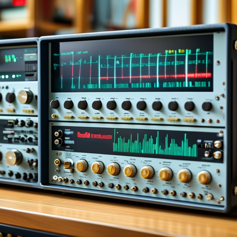
FM Transmitters: Definition, Purpose, and Core Functions
FM transmitters convert audio into radio-frequency signals that receivers can decode. A microphone creates a changing electrical voltage. The transmitter uses that voltage to vary a carrier wave’s frequency, rather than its amplitude. This process is frequency modulation, or FM. The signal then passes through an exciter, power amplifier, and antenna. The antenna releases the finished signal into the surrounding space.
The purpose is practical: deliver clear audio across a defined coverage area. A transmitter may serve a broadcast site, a community facility, or a small private system. ITU-R Recommendation BS.450-4 describes key FM broadcasting parameters, including a 15 kHz audio bandwidth and a 19 kHz stereo pilot. These details help receivers separate music, speech, and stereo information accurately. The result is not magic. It is controlled electrical movement.
Core functions include signal generation, modulation, filtering, amplification, and antenna matching. A poorly matched antenna can waste power and create unwanted heating. In practice, the neat diagram often lies. Cable loss, terrain, weather, and nearby electrical noise affect real coverage. RAJAR’s Q1 2024 measurement reported 88.7% weekly radio reach among UK adults, showing why reliable transmission still matters. Yet audience reach does not prove perfect engineering. Technicians must measure field strength, check frequency stability, and review audio levels regularly. One small adjustment can change reception several streets away.
What Are FM Transmitters and How Do They Work? - FM Transmitters: Definition, Purpose, and Core Functions
| Data Dimension | Typical Information | Explanation |
| Definition | Radio-frequency signal transmitter | An FM transmitter converts audio or other information into a radio signal by varying the frequency of a carrier wave. |
| Primary Purpose | Wireless audio distribution | It sends audio content through the air so compatible receivers can recover and reproduce the original program. |
| Modulation Method | Frequency modulation | The instantaneous frequency of the carrier changes according to the amplitude of the input audio signal, while the carrier amplitude remains approximately constant. |
| Common Broadcast Band | Approximately 88–108 MHz | This is the widely used FM broadcast band in many countries. The exact allocation differs by region. |
| Input Signal | Analog or digital audio | The input may come from microphones, mixers, playback systems, computers, or digital audio processors. |
| Audio Processing | Filtering, compression, and level control | Processing prepares the audio for transmission, limits excessive peaks, and helps maintain consistent loudness. |
| Carrier Frequency | A selected frequency within the permitted channel range | The carrier provides the radio-frequency center around which the modulated signal is transmitted. |
| Frequency Deviation | Often up to ±75 kHz for wideband FM broadcasting | Deviation describes how far the carrier frequency moves above or below its center frequency. Actual limits depend on the transmission standard. |
| Main Signal Chain | Audio input → processing → modulation → amplification → antenna | Each stage conditions the content, places it on the carrier, increases usable power, and radiates it as electromagnetic energy. |
| Power Amplifier | Raises the radio-frequency output power | The amplifier increases signal power before the signal reaches the antenna. Power levels vary widely by application and authorization. |
| Antenna Function | Radiates the RF signal | The antenna converts electrical radio-frequency energy into electromagnetic waves that propagate through space. |
| Receiver Compatibility | FM radio receiver or tuner | The receiver selects the desired frequency, demodulates the FM signal, and converts the recovered audio into an output signal. |
| Noise Resistance | Generally better than AM for many types of amplitude noise | Because information is represented by frequency changes rather than carrier amplitude, many amplitude variations can be reduced during reception. |
| Transmission Range | Depends on power, antenna height, terrain, and frequency | FM signals in the broadcast band primarily travel by line of sight, so obstacles, terrain, antenna placement, and receiver sensitivity affect coverage. |
| Typical Applications | Broadcasting, local information, events, and short-range audio links | Applications include public radio services, educational programming, venue announcements, and localized audio transmission. |
| Regulatory Requirement | Frequency, power, bandwidth, and emissions compliance | Operation normally must follow the radio regulations of the relevant jurisdiction, including authorized frequencies and maximum permitted power. |
Note: Technical values are typical reference figures. Actual operating limits and channel allocations vary according to the applicable national or regional regulations.
The Main Components Inside an FM Transmitter
An FM transmitter turns sound into controlled changes in radio frequency. Its main components work as a carefully balanced chain. The audio input accepts a microphone or line-level signal. A preamplifier raises weak signals without adding excessive noise. Pre-emphasis then boosts selected high frequencies before modulation. This improves clarity after reception.
The oscillator creates a stable carrier, commonly within the 87.5–108 MHz broadcast range identified in ITU-R BS.450-4. A modulator varies that carrier with the audio waveform. The buffer stage isolates the oscillator from later circuits. This prevents unwanted frequency drift. A driver and RF power amplifier then increase signal strength. Heat sinks matter here. Poor cooling can reduce output stability and shorten component life.
The final stages include a low-pass filter, impedance-matching network, antenna, and regulated power supply. The filter removes harmonic energy before the signal reaches the antenna. The matching network helps transfer power efficiently. In practical inspections, loose connectors often cause more trouble than complex circuitry. That detail is easy to overlook. The FCC’s 47 CFR §15.239 sets a 250 μV/m field-strength limit at three meters for certain unlicensed emissions in the FM band. Licensed systems follow different requirements. Measurements still matter more than appearance. A bright display does not prove a clean signal. My simplified explanation also has limits: transmitter designs may add digital signal processing, automatic gain control, and monitoring circuits. Those additions improve control, but they can hide distortion when configured poorly.
How Audio Signals Become FM Radio Waves
A transmitter does not send sound directly. It sends a changing radio signal that represents sound. A microphone first detects moving air, such as a spoken voice or a guitar string. Its diaphragm vibrates and creates a small electrical audio signal. This signal is usually strengthened and filtered before transmission.
Here is the key step. A stable oscillator produces a carrier wave at a chosen frequency. The audio signal then changes that carrier’s frequency, not its basic strength. This process is frequency modulation, or FM. A louder audio voltage causes a wider frequency shift. A quieter signal creates a smaller shift. The combined signal passes through filtering and amplification. An antenna converts it into electromagnetic waves that travel through space.
The process is precise, but not perfect. Electrical noise, poor grounding, and nearby signals can affect clarity. Buildings and hills may also reflect the waves, creating brief distortion in a moving car. On a test bench, a steady 1 kHz tone produces a smooth repeating frequency change. Speech looks far less tidy. It rises, falls, and pauses constantly.
A receiver captures the wave with its antenna. Its tuner selects the intended frequency. A demodulator then follows the carrier’s frequency changes and rebuilds the original audio signal. An amplifier drives the speaker, which moves air again. The final sound is not the original vibration exactly. It is a carefully reconstructed version. That small difference matters when engineers check signal quality, bandwidth, and legal transmission limits.
How FM Signals Travel from the Transmitter to a Receiver
What Are FM Transmitters and How Do They Work?
An FM transmitter converts sound into a changing radio-frequency signal. A microphone first turns voice or music into electrical audio. The transmitter then varies the carrier wave’s frequency, while its amplitude remains nearly constant. This process is called frequency modulation. ITU-R BS.450-4 describes FM broadcasting with a maximum deviation of about 75 kHz in common wideband systems. That figure helps engineers control clarity, coverage, and interference.
The signal leaves the antenna as electromagnetic energy. It travels outward at nearly the speed of light. Some energy follows the ground, while higher-frequency components can reflect, diffract, or weaken around buildings. A receiver’s antenna captures only a small portion of this field. Its tuner selects the desired channel, and its demodulator extracts the original audio. In the United States, FCC regulations commonly allocate 200 kHz between FM broadcast channels. Real reception remains less tidy. Hills, metal structures, multipath reflections, and antenna height can create brief distortion or fading. A city street may sound clean at one corner, then crackle seconds later.
Tips
Place the receiving antenna vertically and away from large metal objects. A higher position often improves line-of-sight coverage. Do not judge performance from one location. Walk several meters and compare the audio. ITU-R propagation guidance shows that terrain and clutter can change predicted field strength substantially. Coverage maps are useful, but field measurements are better. Even careful testing can miss seasonal or weather-related variation. That limitation deserves attention.
Common Types, Uses, and Operating Considerations of FM Transmitters
FM transmitters convert audio into radio signals by varying a carrier frequency. A receiver then turns those variations back into sound. Their design depends on range, power, and operating conditions. Low-power transmitters suit short-distance audio links and approved educational demonstrations. Higher-power systems support authorized broadcast, public information, and large-site communication. Professional exciters usually offer better frequency control and monitoring.
FM transmitters are useful in studios, event venues, training facilities, and emergency communication systems. Clear audio requires more than transmitter power. Antenna placement, cable quality, grounding, and local interference all matter. A poorly tuned antenna can waste energy and reduce coverage. Excessive input levels may cause distortion and unwanted signal spread. Engineers should verify frequency stability, ventilation, and electrical safety before operation. Rules differ between regions, so operators must follow applicable licensing and technical requirements. A simple installation can still fail.
Tips: Keep the transmitter away from heat and moisture. Use a suitable antenna for the intended frequency. Check audio levels with headphones before connecting the system. Measure performance at several locations, not just beside the equipment. Record operating settings for easier troubleshooting. Remember that stronger output is not always better; excessive power can create interference and shorten equipment life. Practical testing often reveals weaknesses that specifications cannot show.
FM Transmitter Types and Typical Occupied Bandwidth
Occupied bandwidth is estimated with Carson’s rule: B ≈ 2 × (maximum frequency deviation + highest modulating frequency). Narrowband FM is commonly used for voice communication, while broadcast FM uses a much wider deviation and audio range for higher-fidelity sound. Actual channel spacing and emissions depend on the applicable radio regulations.