
Top 10 Industrial EMC Solutions for Global Buyers
Industrial EMC is not a box added after a machine fails testing. It is a design discipline that shapes component choices, enclosure details, cable routing, grounding, and verification. For global buyers, the right Industrial EMC Solution must fit the equipment, operating environment, production scale, and service plan—not just a product sheet.
Henry W. Ott, EMC engineer and author of Electromagnetic Compatibility Engineering, describes EMC as “the ability of electronic equipment and systems to function acceptably in their electromagnetic environment.” That principle helps frame this guide. A drive cabinet beside a variable-speed motor faces different interference challenges from a sensor installed on a long factory line. Even a poorly terminated cable shield can matter. Small details matter.
The following overview compares ten industrial EMC approaches, including filters, shielding, surge protection, grounding components, and cable-management options. It considers practical selection factors: attenuation data, installation constraints, compatibility with the equipment, documented testing, and supplier support. Buyers should verify claims against their own operating conditions and independent test evidence where available. A ranking cannot replace engineering review. Nor can one component solve every interference problem.
Some choices may look less compelling once installation labor and maintenance are counted. That is worth admitting. This guide is intended to help buyers ask sharper questions, compare solutions with care, and identify where specialist advice is needed before procurement.
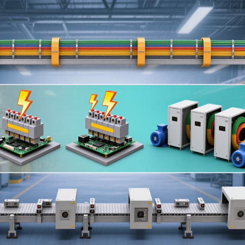
Understanding Industrial EMC and Its Role in Reliable Operations
Industrial electromagnetic compatibility (EMC) helps equipment operate without disrupting nearby systems or failing under electrical interference. In a factory, a variable-speed drive can switch rapidly, while sensor cables carry small signals beside power lines. Poor separation or bonding may introduce noise, causing unstable readings or unexpected resets. The effects can be intermittent, which makes diagnosis frustrating. EMC design addresses both emissions and immunity; it is part of reliable operation, not merely a final compliance test.
The IEC 61000 series provides testing and guidance for electromagnetic emissions and immunity, including requirements for industrial environments. These tests help assess how equipment performs under defined conditions, but they cannot reproduce every plant layout. Uptime Institute’s 2024 Annual Outage Analysis found that 54% of respondents’ most recent significant outages cost more than $100,000. That figure covers outages broadly; it does not identify EMC as their cause. Still, it shows why reducing avoidable operational risks matters.
Tips: Keep signal and power cables separated, bond enclosures properly, and check grounding before commissioning. Test equipment in its intended configuration where practical. Record intermittent faults; they may reveal a pattern. A tidy panel helps, but it does not guarantee immunity.
Top 10 Industrial EMC Solutions for Global Buyers — Understanding Industrial EMC and Its Role in Reliable Operations
| # | EMC Solution | How It Supports Reliable Operations | Typical Industrial Applications | Key Selection or Implementation Considerations | Useful Verification |
|---|---|---|---|---|---|
| 1 | Power-line EMC filters | Attenuate conducted electromagnetic noise entering or leaving equipment through power connections. | Control cabinets, variable-speed drives, switching power supplies, and machine tools. | Match the filter to the supply voltage, current, frequency, installation environment, and expected noise paths. Follow the specified line, load, and protective-earth connections. | Conducted-emissions testing and immunity testing appropriate to the equipment and applicable product standards. |
| 2 | Shielded enclosures and cabinets | Reduce radiated emissions and help protect sensitive circuits from external electromagnetic fields. | Automation controllers, measurement systems, radio-frequency equipment, and sensitive instrumentation. | Evaluate seams, doors, ventilation openings, cable entries, and bonding. A shield can be compromised by gaps or poorly treated penetrations. | Radiated-emissions and radiated-immunity tests; inspect enclosure seams and cable-entry treatment. |
| 3 | Shielded cables with circumferential termination | Limit coupling between cables and nearby electromagnetic sources when the cable shield is correctly connected. | Encoder, sensor, motor, data, and control wiring in electrically noisy environments. | Select cable construction for the signal and environment. Use connectors or clamps that provide a low-impedance, broad-area shield connection where the design requires it. | Inspect shield continuity and termination quality; test the complete installation under representative operating conditions. |
| 4 | Equipotential bonding and protective earthing | Provide controlled paths for fault and interference currents and reduce voltage differences between conductive parts. | Machine frames, control cabinets, cable trays, and interconnected industrial equipment. | Follow electrical safety requirements and local regulations. Use short, reliable bonding connections and avoid relying on painted or corroded surfaces for electrical contact. | Protective-earth continuity and bonding inspections; verify the installation against applicable safety and EMC requirements. |
| 5 | Ferrite suppression components | Add frequency-dependent impedance that can reduce certain high-frequency common-mode currents. | Power, signal, and communication cables exhibiting localized high-frequency interference. | Choose a ferrite material and geometry suited to the frequency range and cable arrangement. Confirm that the component does not create unacceptable heating or affect signal performance. | Compare emissions or interference levels with and without the component across relevant operating conditions. |
| 6 | Surge protective devices | Limit transient overvoltages and divert surge currents, helping protect equipment from specified surge events. | Incoming power distribution, control panels, and signal or communication lines where surge exposure is considered. | Select devices for the system voltage, earthing arrangement, expected exposure, and required protection level. Coordinate protection stages and follow installation instructions. | Review device status and installation; use surge-immunity tests such as IEC 61000-4-5 where applicable. |
| 7 | Galvanic isolation | Interrupt direct conductive paths between circuits, which can help address ground loops and certain conducted disturbances. | Industrial communication links, measurement inputs, control interfaces, and selected power circuits. | Check isolation rating, working voltage, bandwidth, data rate, safety requirements, and the disturbance mechanisms the design is intended to address. | Verify insulation and functional performance; assess conducted immunity and communication integrity in the installed system. |
| 8 | Cable routing and physical separation | Reduce unintended coupling by managing the proximity and routing of noisy and sensitive circuits. | Control cabinets, machine wiring, motor-drive installations, and plant cable routes. | Separate power and low-level signal wiring where practical; minimize parallel runs and use crossings, routing, and segregation practices appropriate to the installation design. | Installation inspection and functional checks during switching, motor start-up, and other representative operating states. |
| 9 | Conductive gaskets and contact treatments | Maintain electrical continuity across enclosure joints and access panels, supporting enclosure shielding performance. | Cabinet doors, removable panels, access covers, and shielded equipment housings. | Consider compression, surface finish, corrosion, environmental exposure, and repeated opening. Ensure the gasket is compatible with the enclosure and its mechanical design. | Inspect contact continuity and enclosure condition; perform radiated testing when shielding performance is critical. |
| 10 | EMC testing and design validation | Identifies emissions and immunity weaknesses before deployment and helps confirm that corrective measures work. | New equipment, design changes, production qualification, and troubleshooting of field interference. | Define the intended markets, product category, operating modes, ports, and applicable standards before selecting tests. Requirements vary by equipment and jurisdiction. | Depending on the product, relevant references may include CISPR 11, IEC 61000-6-2, IEC 61000-6-4, and IEC 61000-4 series test methods. |