
Posts
What Is an M12 Power Connector?
The M12 Power Connector is a compact, circular connector used to deliver electrical power to equipment in industrial environments. Its threaded coupling helps secure the connection against vibration, while its small form supports installations with limited space. Some versions are designed for demanding conditions, but their protection level depends on the specific product and proper mating.
Small, but important.
M12 power connectors differ in pin arrangement, coding, rated voltage, current, and cable options. These details determine whether a connector suits a motor, actuator, sensor system, or other device. An M12 connector intended for data or signal transmission is not automatically suitable for power. Check the equipment documentation and connector datasheet before choosing one. Ratings and compatibility can vary, even when two products look nearly identical.
A catalog photo cannot tell the whole story.
This guide explains how the M12 Power Connector works, what its key features mean, and how to compare common configurations. It also covers practical selection points, such as mating compatibility, environmental conditions, and cable requirements. In real installations, small details can create avoidable problems; connector coding, for example, may be easy to overlook. There is no single M12 power connector for every application. Careful verification is more useful than assuming that a familiar shape guarantees a fit.
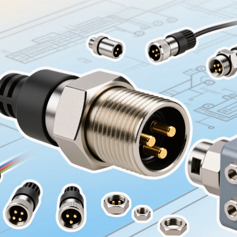
M12 Power Connector Basics: 12 mm Thread and IEC 61076-2-111
An M12 power connector is a circular connector built around a nominal 12 mm threaded coupling. The thread helps secure the connection against vibration and accidental loosening. It is compact enough for crowded machine panels, yet designed to carry power rather than signals alone.
IEC 61076-2-111 specifies requirements for M12 connectors used in power applications, including interface dimensions and connection details. This gives designers a reference when checking whether a plug and socket are compatible. The standard does not mean every M12 power connector has the same pin arrangement, rating, or keying. The fit matters. Check the connector’s coding, contact layout, voltage, and current rating against the equipment documentation.
The label alone can mislead. Inspect the mating face and thread before installation, especially when several connector types sit side by side on a cabinet. Check the sealing surface for dirt or damage, then tighten the coupling as directed by the manufacturer. Do not force a connector that resists turning; mismatched keying or cross-threading can damage the interface. A quick visual check is useful, but it cannot replace the specified electrical ratings.
M12 Power Coding: How S, T, K, L, and M Keying Distinguishes Circuits
M12 power connectors use keyed shells to separate circuit types and reduce mismating. The letter identifies the key shape, not a universal pinout. S- and K-coded connectors are generally intended for AC power; T-, L-, and M-coded versions are used for DC power. Their different internal keyways help prevent incompatible plugs from mating. A small notch can make a big difference.
The codes also relate to contact arrangements and intended loads. S and T designs commonly use four contacts, while K and L designs commonly use five. M-coded designs may provide additional contacts for particular power arrangements. Exact ratings and pin assignments depend on the connector and cable assembly. The letter alone is not enough. Before installation, compare the equipment drawing with the connector’s voltage, current, pole count, and contact layout. Pay close attention to protective earth and polarity. In real panels, labels can be hard to read, and similar-looking connectors invite assumptions. I would verify the pinout even when the coding appears to match. That extra check is easy to overlook.
M12 Power Coding: Typical Contact Positions
M12 power coding uses different key shapes to distinguish connector types and help prevent mismating. Typical layouts have 4 contact positions for S and T coding, 5 for K and L coding, and 6 for M coding. Exact configurations and ratings can vary by connector specification.
Voltage and Current Ratings: Compare Power Codes Before Selecting a Connector
An M12 power connector is a compact, threaded interface for supplying energy to sensors, actuators, and other equipment. Its code matters: the keying pattern helps prevent mismatched connections, while the rated voltage and current define electrical limits. IEC 61076-2-111 specifies M12 power connector interfaces and coding. It does not make every connector with the same code suitable for every installation. Check the product’s technical data sheet.
Compare the code and rating together. S-coded connectors are commonly specified for up to 630 V AC and 12 A; L-coded versions are commonly rated up to 63 V DC and 16 A. These are typical limits, not a guarantee for every model. Check the exact rating, pin configuration, and whether the value applies per contact.
Small details matter. A cable run inside a warm cabinet may need more careful current assessment than a short, open-air connection. IEC 60512 provides test methods for connector electrical performance, but installation conditions still affect selection. I have seen ratings treated like interchangeable numbers; that shortcut deserves a second look.
Use the lowest applicable limit across the connector, cable, and equipment.
Contact Layout and Cable Selection for Industrial Power Loads
What Is an M12 Power Connector?
Contact Layout and Cable Selection for Industrial Power Loads
An M12 power connector carries electrical power to equipment such as sensors, actuators, and compact motors. Its circular, threaded coupling helps resist loosening when machinery vibrates. Contact layouts vary: some connectors use three or four contacts, while others provide additional contacts for specific designs. The pin arrangement and coding matter. Similar-looking connectors may not share the same electrical rating or mating pattern.
Match the contact layout to the equipment’s wiring diagram, supply voltage, and expected current. Never assume a pin assignment from connector shape alone. For cable selection, check the load current, cable length, conductor size, and installation conditions. A long run or a high-current load can increase voltage drop and heat. Flexible machinery may also need cable designed for repeated movement. Jacket material should suit nearby oil, moisture, abrasion, and temperature. It is tempting to choose by outside diameter alone, but that can miss the real constraint.
Tips: Confirm the connector’s rated current and voltage, then check the cable’s conductor area and temperature rating. Leave room for strain relief. I would still verify the complete assembly against the equipment documentation; small details can change the right choice.
Ingress Protection: IP67 Requires a Properly Mated, Sealed Connection
What Is an M12 Power Connector?
Ingress Protection: IP67 Requires a Properly Mated, Sealed Connection
An IP67 rating describes protection under defined test conditions, not every possible installation. For an M12 power connector, the rating generally applies when the plug and socket are fully mated, with their sealing surfaces clean and correctly compressed. Fit matters. A loose coupling nut, trapped grit, or a nicked O-ring can create a path for water. The connector may look secure while its seal is not.
Before mating, check for dust, moisture, and damage around the connector face and gasket. Align the keyway, then tighten the coupling as specified for that connector. Avoid forcing misaligned threads; this can damage the seal or housing. Small details matter. If the connection will remain unmated, use a suitable sealed protective cap rather than assuming the exposed connector retains its IP67 protection. Also inspect cable-entry seals, since water can enter behind the connector even when the mating interface is sound. IP67 commonly refers to dust protection and temporary immersion under specified conditions, but exact test details depend on the applicable specification. It is not a promise of protection against every washdown, chemical, or pressure. Recheck seals after repeated connection cycles. A quick visual check helps, though it cannot replace the manufacturer’s installation instructions.
| Dimension | Typical Information | Practical Meaning |
|---|---|---|
| Connector family | M12 circular connectors use a nominal 12 mm threaded coupling interface. | The M12 designation describes the coupling size; it does not by itself specify the connector’s electrical rating, pin count, or environmental protection. |
| Common coupling thread | M12 × 1 is commonly used for the threaded coupling. | Check the product drawing and mating-interface specification before assembly; the thread alone does not guarantee compatibility or sealing. |
| Power-connector coding | M12 power connectors are available in different codings, including L-, T-, S-, and K-coding. | Coding helps distinguish connector configurations and reduce mismating. Select matching plug and receptacle types for the intended application. |
| Contacts and ratings | Contact count, rated voltage, rated current, and wire range depend on the specific connector design and applicable specification. | Use the ratings stated for the exact connector, cable, and mating pair. Do not infer electrical capacity from the M12 size or IP rating. |
| IP67: first digit | The “6” indicates dust-tight protection under the IP code. | When tested as specified, dust ingress is prevented from entering the enclosure in a quantity that would interfere with operation or safety. |
| IP67: second digit | The “7” indicates protection against temporary immersion under the specified test conditions, generally up to 1 m for 30 minutes. | IP67 is not a claim of suitability for continuous underwater use, high-pressure washing, or every chemical and temperature condition. |
| Mating and sealing condition | An IP67 rating applies only in the configuration and conditions stated by the connector manufacturer. For many connector assemblies, the interface must be fully mated and correctly sealed. | Align the connector, engage the coupling correctly, and tighten it as specified. A loose or partially mated connection may not maintain the stated protection. |
| Unmated connectors | An unmated connector may require a suitable sealing cap to achieve its specified ingress protection. | Do not assume an open receptacle or plug remains IP67. Protect unused interfaces with the specified cap and seal. |
| Installation checks | Inspect sealing surfaces and gaskets for dirt, damage, displacement, or wear; follow the specified assembly and tightening instructions. | Contamination, damaged seals, incorrect assembly, or cable-entry problems can compromise protection even when the connector is marked IP67. |
| Application limits | IP67 describes ingress protection against dust and temporary immersion, not electrical performance or resistance to every environmental hazard. | Also verify temperature range, vibration resistance, chemical compatibility, cable requirements, and electrical ratings for the operating environment. |
