What Is a Pneumatic Butterfly Valve and How Does It Work?
A Pneumatic Butterfly Valve uses compressed air to turn a disc inside a pipe, controlling or isolating flow. The disc rotates around a central shaft, usually through a quarter turn. Simple motion. In practice, an actuator converts air pressure into rotation, while a positioner or solenoid valve may direct the movement. When the disc aligns with the flow, fluid passes; when it turns across the pipe, flow is restricted or stopped. The seal, disc, body, and actuator all affect how reliably this happens.
These valves are common in water treatment, HVAC, chemical processing, and other systems where compact, quick operation is useful. A technician may hear the actuator cycle and see a position indicator shift, but those clues alone do not confirm a tight seal. That matters. Pressure, temperature, fluid properties, seat material, and installation alignment can change performance. A butterfly valve may also allow some leakage when closed, depending on its design and service conditions. It is worth checking the manufacturer’s specifications rather than assuming every model behaves the same.
This guide explains the main components, the operating sequence, and the differences between common actuator arrangements. It also covers selection and maintenance considerations, including air supply quality and routine inspection. The basic principle is straightforward; choosing the right valve is less so. Engineers should verify sizing, materials, and fail-safe behavior against actual process requirements. A small mismatch can create persistent operating problems. That can be overlooked.
Definition and Service: A Quarter-Turn Valve for On-Off or Throttling Duty
A pneumatic butterfly valve uses a rotating disc to control flow inside a pipe. The disc turns about a quarter-turn, from open to closed, while an air-powered actuator supplies the movement. In the open position, the disc sits roughly parallel to the flow. Turned across the pipe, it restricts or stops the stream. The compact arrangement is useful where space and quick operation matter.
For on-off duty, the actuator moves the disc between its end positions. A positioner or control signal can instead hold it at an intermediate angle for throttling. This changes the flow area, but not in a perfectly linear way: small disc movements may cause uneven changes in flow. The process conditions matter. Pressure, temperature, fluid properties, and required shutoff performance all affect valve selection.
In a plant room, air pressure drops or a sticky linkage can slow the response. Check the air supply, actuator travel, and disc movement during routine inspections. Listen for leaks. Also confirm that the valve is suitable for frequent cycling; not every butterfly valve handles continuous throttling well. A tidy installation helps, though real piping rarely stays tidy for long. The valve’s position feedback can help operators spot a mismatch between the commanded position and the disc’s actual travel.
Main Components: Body, Disc, Stem, Seat, and Pneumatic Actuator
A pneumatic butterfly valve uses a rotating disc to control flow through a pipe. The body holds the assembly and fits between or onto pipe connections. Inside it, the disc turns across the flow path. When open, its edge aligns with the moving fluid; when closed, it presses against the seat. The seat forms the sealing surface, so its material must suit the fluid, temperature, and operating conditions. Small details matter.
The stem connects the disc to the pneumatic actuator, which converts compressed air into rotation. A quarter-turn movement is typical. Some actuators use air to open and close the valve; others use a spring to return it when air supply is lost. The right arrangement depends on the process, not just convenience. In practice, a valve that looks correctly sized may still perform poorly if the actuator lacks enough torque under actual pressure conditions. That is easy to overlook. Check the valve’s operating range, seat compatibility, and air supply before installation, and inspect for wear or leakage during maintenance. Even a small seat defect can affect shutoff.
What Is a Pneumatic Butterfly Valve and How Does It Work?
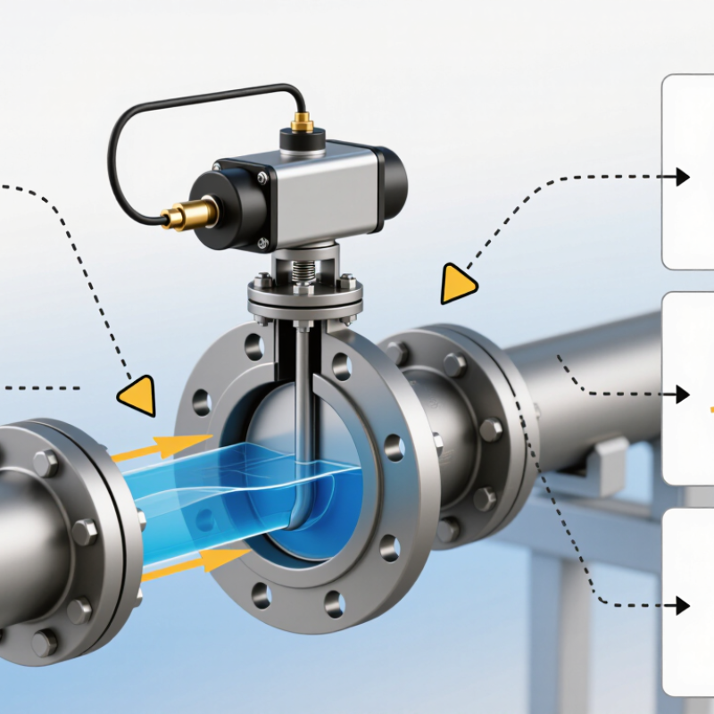
A pneumatic actuator turns the valve stem, rotating the disc through a quarter-turn to open or close the flow path.
Main components: The body contains the flow path; the disc regulates flow; the stem transfers actuator torque to the disc; the seat provides the sealing surface; and the pneumatic actuator uses compressed air to move the valve. The chart shows an illustrative one-second, 90-degree opening stroke—not a guaranteed operating specification. Actual stroke time depends on valve and actuator sizing, air pressure, and operating conditions.
How It Works: The Disc Rotates 90° Between Open and Closed Positions
What Is a Pneumatic Butterfly Valve and How Does It Work?
How It Works: The Disc Rotates 90° Between Open and Closed Positions
A pneumatic butterfly valve uses compressed air to turn a circular disc inside a pipe. In the open position, the disc aligns with the flow, leaving a broad passage. Air enters the actuator and moves a piston or rotary vane. The actuator transfers this motion through the stem, turning the disc about 90 degrees. A quarter turn. In the closed position, the disc sits across the flow path and presses against a seat to restrict flow. The movement is simple, but the seal and actuator must suit the fluid, pressure, and operating frequency.
Between the end positions, the disc can regulate flow, though it may not provide precise control in every application. A practical check is to confirm actuator torque at the actual differential pressure; a valve that turns freely on a bench may behave differently in a loaded line. ISO 5211 covers mounting interfaces for part-turn actuators, helping engineers check mechanical compatibility. The U.S. Department of Energy’s Improving Compressed Air System Performance sourcebook notes that compressed-air systems can account for about 10% of industrial electricity use, and sometimes more. That makes air leaks and actuator sizing worth checking—not because this valve alone drives energy use, but because every air-powered device adds demand. Spring-return actuators can move the disc to a chosen position after air loss, if specified and configured for that response. The detail is easy to overlook.
Actuation and Mounting: Compressed Air, Torque, and ISO 5211 Interfaces
A pneumatic butterfly valve turns a circular disc inside the pipe. Compressed air moves a piston or rotary vane, which rotates the stem and disc. A quarter-turn usually moves the disc between open and closed positions. The motion looks simple. The torque calculation is not. Required torque changes with valve size, pressure difference, seat friction, and wear. An actuator should provide enough torque across the full stroke, with a suitable margin—not merely match a nominal valve size.
Air quality and supply pressure matter too. Low pressure can leave the disc short of its intended position; leaks waste energy and make operation less predictable. The U.S. Department of Energy’s Improving Compressed Air System Performance sourcebook reports that leaks can waste 20 to 30 percent of compressor output in some plants. That figure is a useful warning, not a prediction for every site. ISO 5211 defines interfaces for mounting part-turn actuators, including flange and drive connections. Matching the interface helps align the actuator with the valve stem, but it does not confirm correct torque or stroke settings. Check both. A real installation may still surprise you: friction changes, and air pressure fluctuates.
Design and Ratings: API 609 Categories, Pressure Limits, and Valve Sizing
A pneumatic butterfly valve uses a compressed-air actuator to rotate a disc about a quarter turn. The disc sits inside the pipe. At full open, it turns parallel to the flow; at closed, it blocks the passage. Simple motion. API 609 classifies butterfly valves into Category A and Category B designs. Category A valves are generally concentric, with a resilient seat around the disc. Category B valves use an offset design, which can reduce seat wear and suit more demanding service. The category alone does not set a universal pressure limit.
Check the valve’s pressure-temperature rating against the actual process conditions. Body material, seat construction, connection style, and temperature all affect the allowable rating. A printed pressure value is not enough. For example, hot fluid may lower the permitted pressure even when the same valve handles a higher rating at ambient temperature. Confirm the rating in the manufacturer’s technical documentation, and account for pressure surges where relevant.
Sizing depends on flow rate, fluid properties, and the pressure drop across the valve. Engineers commonly use the valve’s flow coefficient, Cv, to compare capacity at a given opening. Oversizing can make control touchy: a small disc movement may cause a large flow change. Actuator sizing matters too. It must provide sufficient torque for the differential pressure, seat friction, and available air supply. Leave a suitable margin, but verify the assumptions; real installations can differ.