What Is an FAU in Fiber Optics?
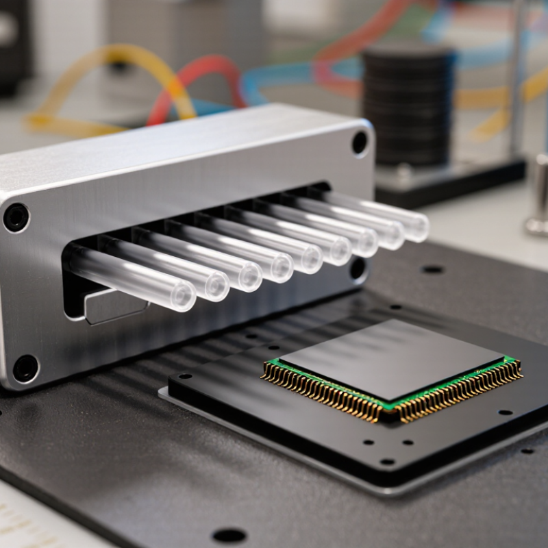
A fiber array unit (FAU) is a precision component that holds multiple optical fibers in a defined pattern. It aligns those fibers with chips, waveguides, or other optical devices. In a photonics assembly, even a tiny positional error can reduce coupling efficiency. Think of several glass fibers meeting a chip face, each requiring careful placement. Small parts. Demanding work.
Fiber-optics pioneer Donald Keck’s research offers a useful engineering lesson, paraphrased here rather than quoted verbatim: “Consistent optical performance depends on controlling loss and variation.” That principle matters when evaluating an FAU. Its performance can depend on fiber pitch, end-face quality, alignment tolerance, and packaging stability. The exact requirements vary by application, so one specification rarely fits every design.
This introduction looks at what an FAU is, how it is built, and where it is used in fiber-optic systems. It also considers practical selection factors, including channel count, fiber spacing, and connector or chip interface. A clean drawing may suggest simple alignment. Real assemblies can be less forgiving. Dust, thermal changes, and manufacturing variation all deserve attention. Not every detail has a neat answer, either; measurement methods and acceptance limits may differ between suppliers. Understanding those limits helps engineers compare FAUs with clearer expectations and ask better questions before integration.
Definition and Role of an FAU in Fiber Optics
An FAU, or fiber array unit, is a component that holds multiple optical fibers in a precise, fixed arrangement. The fibers sit in carefully formed grooves, often on a glass or silicon substrate. Their polished ends create a shared optical interface. Small spacing errors can reduce the amount of light entering a connected device.
In fiber-optic systems, an FAU helps align fiber channels with components such as waveguides, optical switches, or photonic chips. It can support compact connections where many fibers must meet matching optical paths at once. Alignment matters. Even a slight offset may increase insertion loss or weaken a channel. During assembly, technicians check fiber pitch, end-face quality, and the angle of contact. Cleanliness matters too; a speck of dust can affect performance.
An FAU is not simply a bundle of fibers. Its geometry is engineered for repeatable positioning and stable coupling. Still, the best design depends on the application, and tight alignment alone does not guarantee low loss. That part is easy to overlook. Material choice, bonding, and temperature changes can also influence long-term stability. In practice, an FAU serves as a precise bridge between fiber connections and optical components, with its value measured by reliable alignment across every channel.
Main Components and Physical Structure of an FAU
What Is an FAU in Fiber Optics?
Main Components and Physical Structure of an FAU
An FAU, or fiber array unit, holds several optical fibers in a precise, fixed arrangement. It provides a stable interface between the fibers and an optical device, such as a photonic chip. Each fiber must meet its intended position and angle. Small errors matter.
The central structure is often a grooved substrate, commonly made from glass, silicon, or ceramic. V-shaped grooves guide individual fibers and set their spacing. A cover plate may press the fibers into place, while a small amount of adhesive helps secure them. The fiber ends are cleaved and polished into a shared end face, so light can pass between fibers and the device. Some designs add a base or housing for support, but the exact parts depend on the application.
Look closely, and the assembly is less simple than it appears. A fiber may shift slightly as adhesive cures, or the end face may need careful inspection for chips and residue. A polished surface can look clean yet still have alignment issues. That is why manufacturers check pitch, end-face quality, and fiber position under suitable measurement equipment. The neat cross-section on a drawing can hide a surprisingly delicate assembly.
How an FAU Aligns and Couples Optical Fibers
An FAU, or fiber array unit, holds several optical fibers at precise, repeatable intervals. Its job is not just to keep fibers together. It positions each fiber so light can pass between the fiber ends and matching optical channels on a photonic device. In many designs, fibers rest in small V-shaped grooves, which set their spacing and help control their height. Small details matter.
During assembly, technicians align the fiber ends with the device’s optical ports. A camera or microscope can show whether the fibers are centered and whether their end faces sit at the correct distance. The parts may be adjusted in tiny steps while light is sent through them. If the signal reaching the detector is weak, the alignment may need further adjustment. Adhesive then holds the assembly in place, though curing can sometimes shift it slightly.
Good coupling depends on more than visual alignment. Fiber pitch, end-face angle, cleanliness, and the device’s port geometry all affect how much light enters each channel. Some systems couple light directly; others use lenses to spread or focus the beam. The exact method depends on the design. And a neat-looking alignment is not always an efficient one, so measured optical power remains important. Dust can be hard to see, yet still cause trouble.
Common FAU Types and Their Applications
A fiber array unit (FAU) holds several optical fibers at fixed spacing and aligns them with a photonic chip or optical component. Its geometry helps maintain consistent coupling, especially when many channels must connect at once. V-groove FAUs seat bare fibers in precisely formed channels. They are common in planar lightwave circuits, arrayed waveguide gratings, and optical switches. Pitch matters. Even a small alignment error can increase insertion loss across the array.
Capillary FAUs guide fibers through small holes in a glass or ceramic block. They suit applications needing robust positioning, including multi-channel connectors and some optical test assemblies. Ribbon-based FAUs keep fibers in a flat row, making them useful for parallel links and compact modules. Angled or polished fiber ends may also be specified to reduce unwanted reflections. The best type depends on fiber count, spacing, wavelength, and packaging constraints. There is no universal choice. A design that works on a bench may need adjustment inside a heated enclosure, where materials expand differently. That detail is easy to overlook.
Key Factors in FAU Design and Performance
What Is an FAU in Fiber Optics?
A fiber array unit (FAU) holds several optical fibers in a fixed pattern. It connects those fibers to components such as photonic chips. Each fiber must meet its corresponding optical port with precise alignment. Even a tiny offset can increase signal loss. Small errors matter.
Pitch, or the spacing between fibers, is a central design choice. It must match the target component, not just the connector drawing. Fiber diameter, core position, and end-face polish also affect coupling. A clean, flat end face helps light pass efficiently; dust or a slight angle can disrupt it. There is no single tolerance that suits every assembly.
Mechanical stability matters too. Adhesives, mounting pressure, and temperature changes can shift fibers over time. In practice, inspection should include both alignment measurements and optical tests, such as insertion-loss checks. A drawing may look perfect and still hide assembly stress. That detail is easy to underestimate. Reliable FAU performance comes from matching the design to its operating conditions, then verifying the finished unit under realistic handling and temperature changes.
What Is an FAU in Fiber Optics?
A Fiber Array Unit (FAU) holds optical fibers in a precise, repeatable arrangement for coupling light to components such as photonic chips. Fiber pitch—the center-to-center spacing between fibers—is a key design dimension.
Design insight: With a nominal 125 µm cladding diameter, a 127 µm pitch leaves just 2 µm between adjacent bare claddings. This close spacing makes accurate grooves, fiber placement, and end-face alignment important. Actual FAU dimensions vary by application.